Xbeam™ LTE EX 0.5 – 6 GHz
Antennas, IIoT and ConnectivityBenefits
The antenna can be utilized in:
- 4G / 5G / LTE
- WLAN
- WI-FI
- ZIGBEE
- Other 0.5 – 6 GHz applications
-
Description
Marking
ATEX:
Ex II 2 G Ex eb mb IIC T6 Gb
Ex II 2 D Ex tb IIIC T85 °C Db
IECEx:
Ex eb mb IIC T6 Gb
Ex tb IIIC T85 °C Db
NRTL:
Class I Zone 1, AEx eb mb IIC T6 Gb
Class II Zone 21, AEx tb IIIC T85°C Db
Class I, Division 2, Grps A, B, C, D, T6
Class II, Division 2, Grps F, G, T85°C
Ambient Temperature
-40°C ≤ Ta ≤ +60°C
Certification
-
ATEX zone 1/21
- EN
-
IECEx zone 1/21
- EN
-
NRTL MET C1D2
- EN
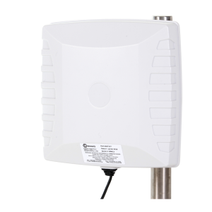
The Xbeam™ LTE EX is an ATEX ,IECEx and NRTL/MET approved RF antenna for creating wireless networks (typically 4G/5G/ LTE) and wireless telemetry systems in hazardous area. The antenna is not limited to a specific network protocol and can be used for any 0.5 – 6 GHz application. The antenna is optimized for use in steel and concrete structure environments where multipath effects and reflections are present.
The Xbeam LTE EX is a preferred solution where the access point/radio can be placed in safe zone or safe area and where cable length does not exceed 30 meters. The antenna can also be used with Ex e, Ex d or Ex p solutions.
Technical Data
| Compatibility | 4G / 5G / LTE / WLAN / Wi-Fi / ZIGBEE or other 0.5 – 6 GHz applications |
|---|---|
| Frequency | 0.5 – 6 GHz |
| Polarization | Vertical |
| Max input voltage | 20 V (EX limitation) |
| Max input power | IIA – 6 W, IIB – 3,5 W, IIC – 2 W |
| RF coonections | RP-TNC or N-TYPE |
| Cable | RADOX OFL RF 142 (MUD approved) 50 Ohm, 8 GHz, 105°C, ø5.34 mm NEK 606 Compliant |
| Height | 118 mm |
| Width, diameter | Ø 140 mm |
| Mounting method | Fixing holes bracket, 4x Ø11 mm, equally spaced on b-c Ø114,2 mm |
| Weight, incl bracket | 1220 g |
| Ingress protection | IP66/IP67 |
Manuals/Operating Instructions/Guides
- EN
- FR
Declarations
- DE
- EN
- NO
Data Sheets