Ethernet / LWL T-Coupler
Automation Interfaces, Couplers, EthernetBenefits
- Bridging of great distances
- Noice-immune signal transmission
- Galvanic isolation
- Fiberview for fiber optic ring monitoring
-
Description
Marking
Ex II 2(1)G Ex db e [ib] IIC Gb
Ex I M2 Ex db e [ib] I Mb
Ex db e [ib] IIC Gb
Ex db e [ib] I Mb
Class I Zone 1 IIC
A/Ex d e [ib] IIC Gb
Fitting (17-1923-1122/0000):
Ex II (2) G / II (2) D
[Ex ib Gb] IIC
[Ex ib Db] IIIC
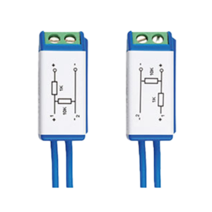
Optical waveguide, Transmitter (17-2114-0002):
Ex II 2 G / II 2 D
Ex ib op is IIC T4 Gb
Ex ib IIIC TX* °C Db
Optical waveguide, Receiver (17-2114-0003):
Ex II 2 G / II 2 D
Ex ib IIC T4 Gb
Ex ib IIIC TX* °C Db
Ambient Temperature
-25 °C to +60 °C at T4
Certification
-
ATEX
- DE
- EN
-
IECEX
- EN
-
CSA
- EN
-
INMETRO
- PT
- PT
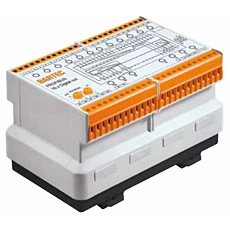
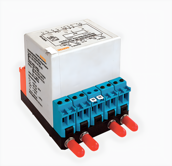
The Ethernet LWL – coupler reroutes the PROFINET from copper conductors to optical waveguides. The coupler is a passive bus participant and are suitable for hazardous areas of zone 1 and 21. In plants, the LWL – coupler allows the bridging of great distance with PROFINET without noice interference. The electronics for the signal conversion are accomodated in the flameproof MODEX enclosure. Transmitter and receiver for the LWL-coupler are intrinsically safe headed. The intrinsically safe control transmitter and receiver of the electronic system guarantee that the transmitter rate does not go beyond maximum value limits.
The Ethernet PCB transmits all types of Ethernet data, including Profinet packets.
Technical Data
| Protection class | At least IP 20 |
|---|---|
| Structure | Clip-on enclosure to TH 35 |
| Dimensions | see data sheet |
| Material | High-quality thermoplastic |
| Storage temperature | -40 °C to +70 °C |
| Weight | 600 g |
| Display | LED Green: Operation indicator (ON)
L/A: FV1 and FV2: Declaration: |
| Voltage | Supply voltage: DC 20 V to DC 30 V |
| Power dissipation | max. 3,0W |
| Bus interface | Bus input/output: 4 wire ethernet with screw terminals LWL input/output: ST Optical fibre plug-in connectors |
Other
- .STP
Manuals/Operating Instructions/Guides
- DE
- EN
Declarations
- DE
- EN
- FR
Data Sheets
Brochures
- DE
- EN